¶ MaxmakeLab 3D Probe Usage
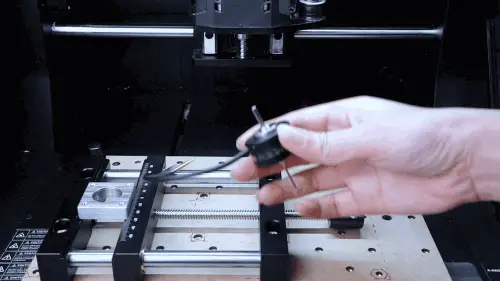
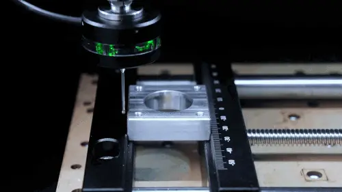
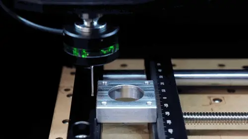
¶ 1. Installing 3D Probe
After installing the 3D probe, switch to the tool setting (3D probe) interface in the software. You need to click the "Tool Change" button and wait for the 3D probe to complete automatic height measurement before proceeding with subsequent operations.
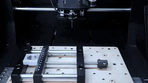
Click the "Tool Change" button:
Install the 3D probe, click the button, and complete automatic height measurement
⚠️ Tool Change Operation Precautions:
- If the workpiece is tall, please adjust the spindle height upward as necessary
- If you need to use the 3D probe to automatically set Z0, this step must be completed, otherwise subsequent tool compensation will be incorrect. After use, you need to click tool change, replace the tool and automatically measure tool height before processing
- If only used for centering or corner detection (setting XY0), this step can be skipped, but when changing the first tool, you still need to click tool change and complete automatic height measurement. Then manually set Z0
- After inserting the 3D probe, do not open the spindle, otherwise it will cause damage to the 3D probe!!!
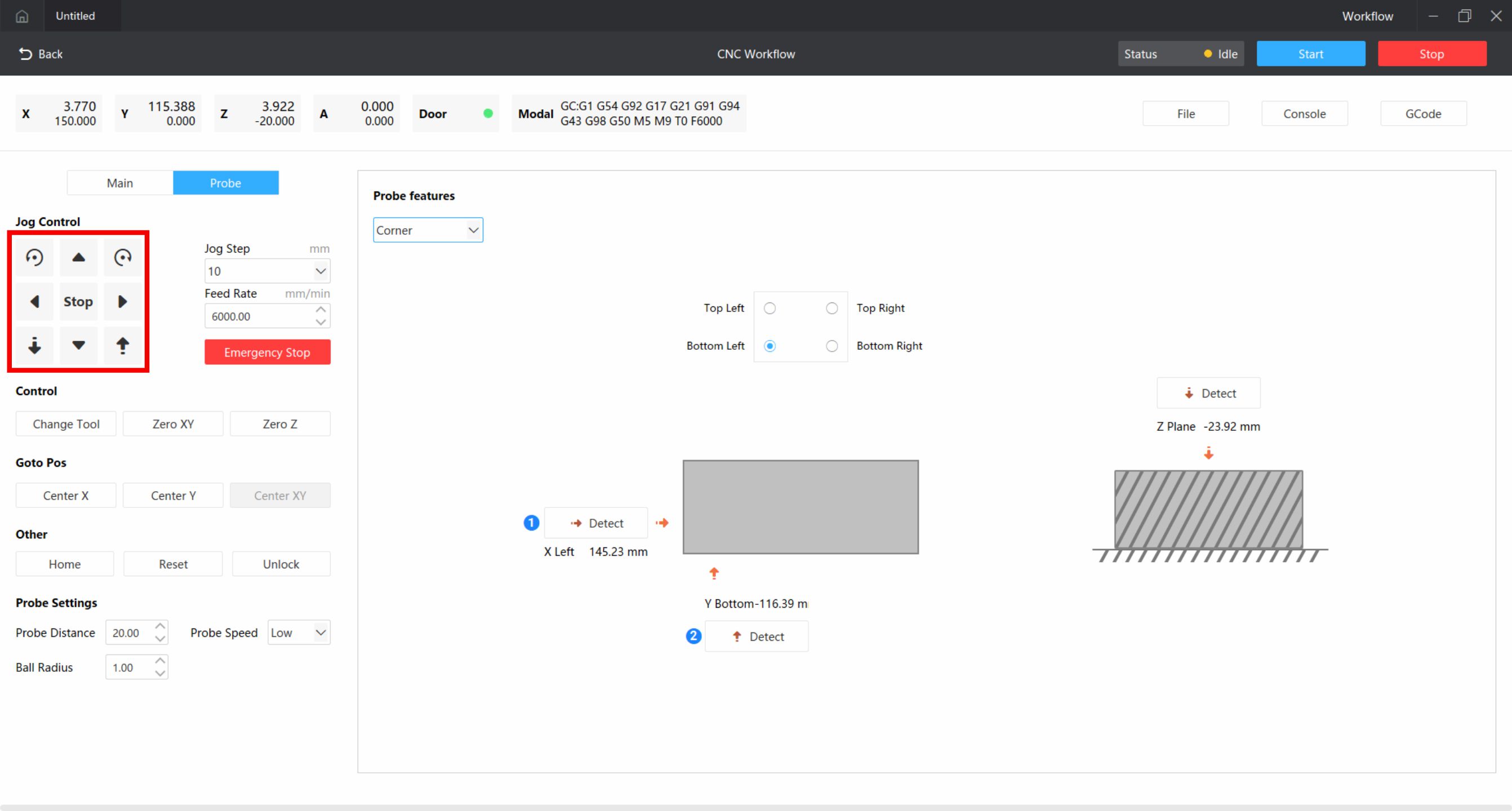
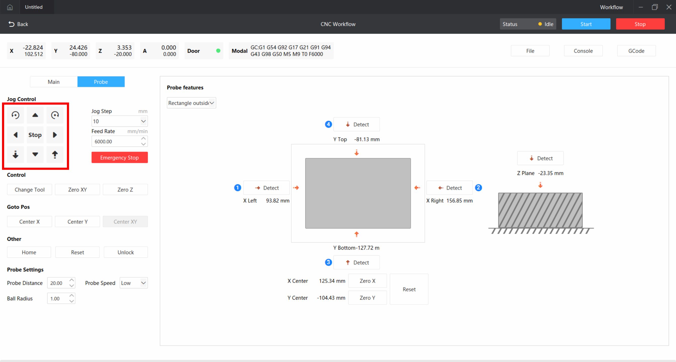
¶ 2. Interface Button Function Introduction
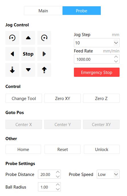
Control:
- Tool Change: Click before installation and install 3D probe, after measurement click and replace with processing tool
- Set XY0: Set current position as XY0 point, used for manual setting. Ignore if using automatic centering
- Set Z0: Set current position as Z0 point, used for manual setting. Ignore if using automatic centering
Move to Position: Center X, Center Y, Center XY. After using 3D probe to set XY0, the corresponding icon will be lit, click to automatically go to the set X0 or Y0 position (also applies to corner detection).
Tool Setting:
- Tool Distance: The distance the probe will move during detection. If no workpiece is detected within the set distance, a popup will prompt
- Tool Speed: The probe will move at the speed set here during detection
- Ball Radius: The ball tip radius of the probe. This is the default value, no changes needed
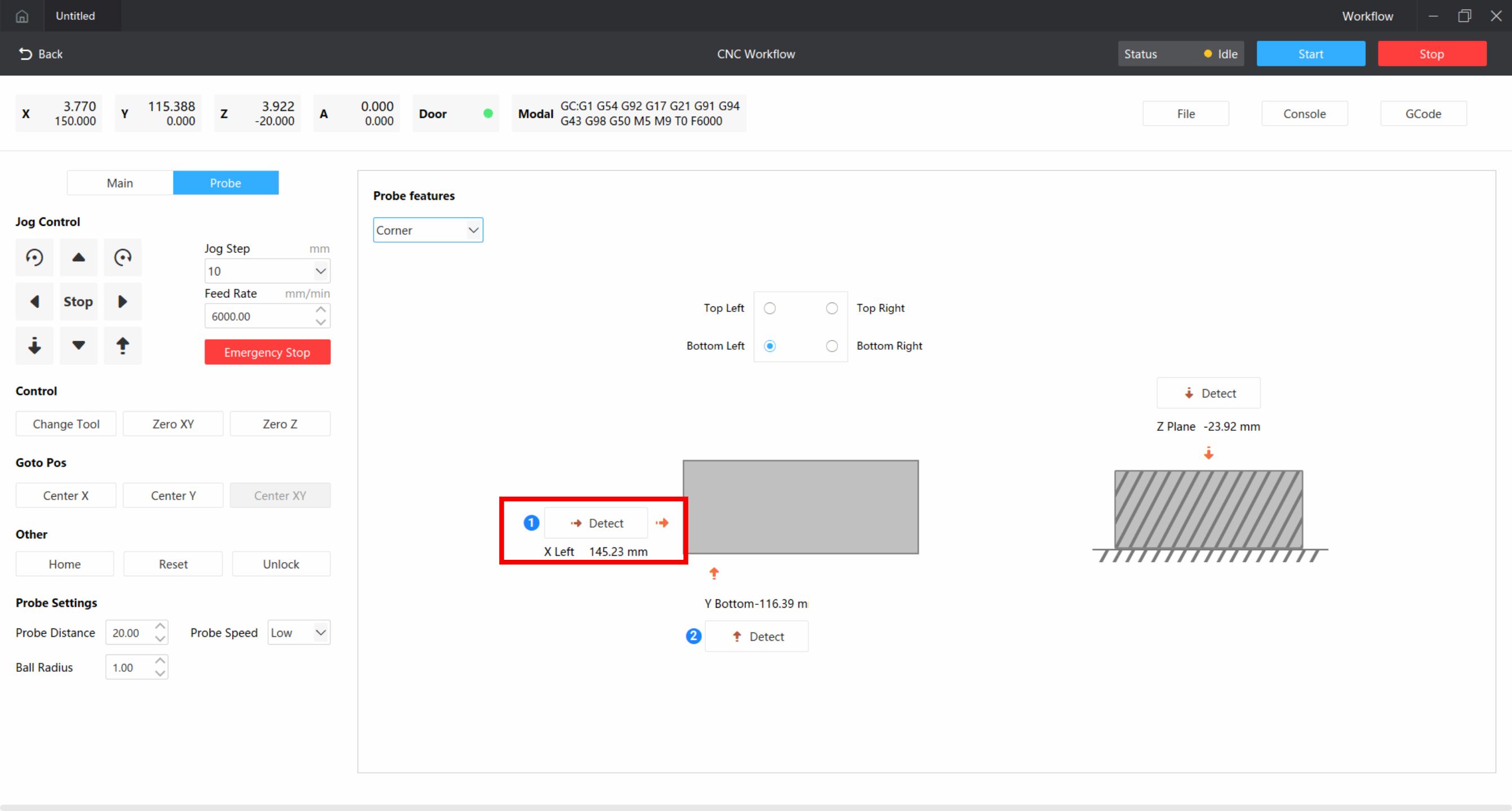
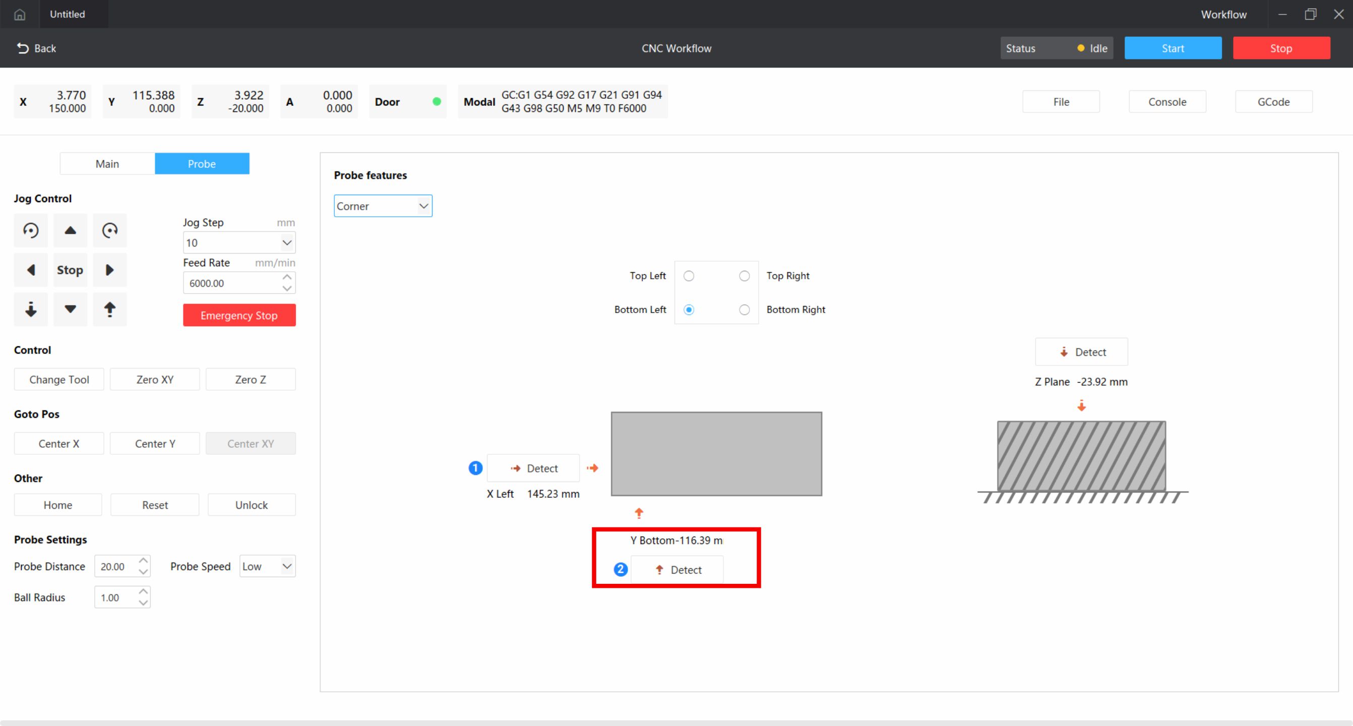
¶ 3. Corner Detection
Select corner detection in the software to detect the corner position of the material and automatically set the corner as XY0. Take the bottom-left corner as an example.
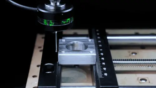
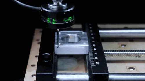
¶ X-axis Detection
Use the movement function to move the 3D probe to the left side of the workpiece.
Click detect, after detecting the workpiece, it will automatically set the detected position as X0.
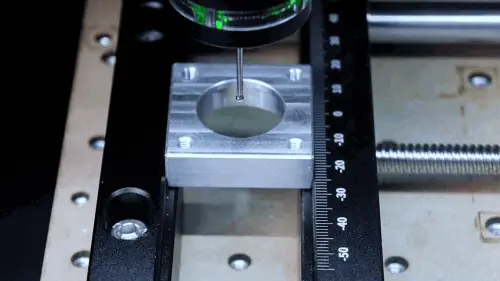
¶ Y-axis Detection
Use the movement function to move the probe to the front side of the workpiece.
Click detect, after detecting the workpiece, it will automatically set the detected position as Y0.
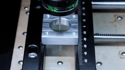
¶ Z-axis Detection
Use the movement function to move the 3D probe above the workpiece.
Click Z-plane detection, after detecting the workpiece, it will automatically set the detected position as Z0.

¶ Tool Change
After all settings are complete, click tool change to replace the first tool to be used and complete automatic height measurement.


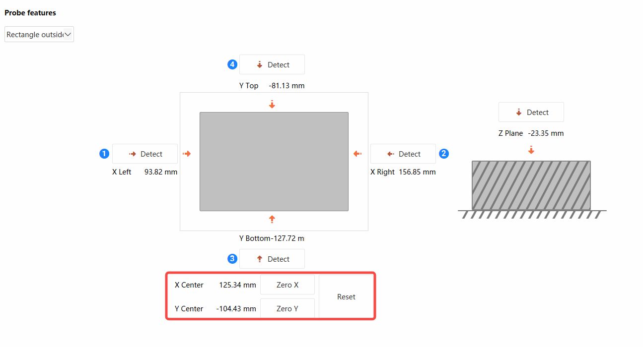
¶ 4. Rectangular External Centering
Select rectangular external centering in the software to detect and automatically calculate the center position, manually set the detected center as XY0 point.
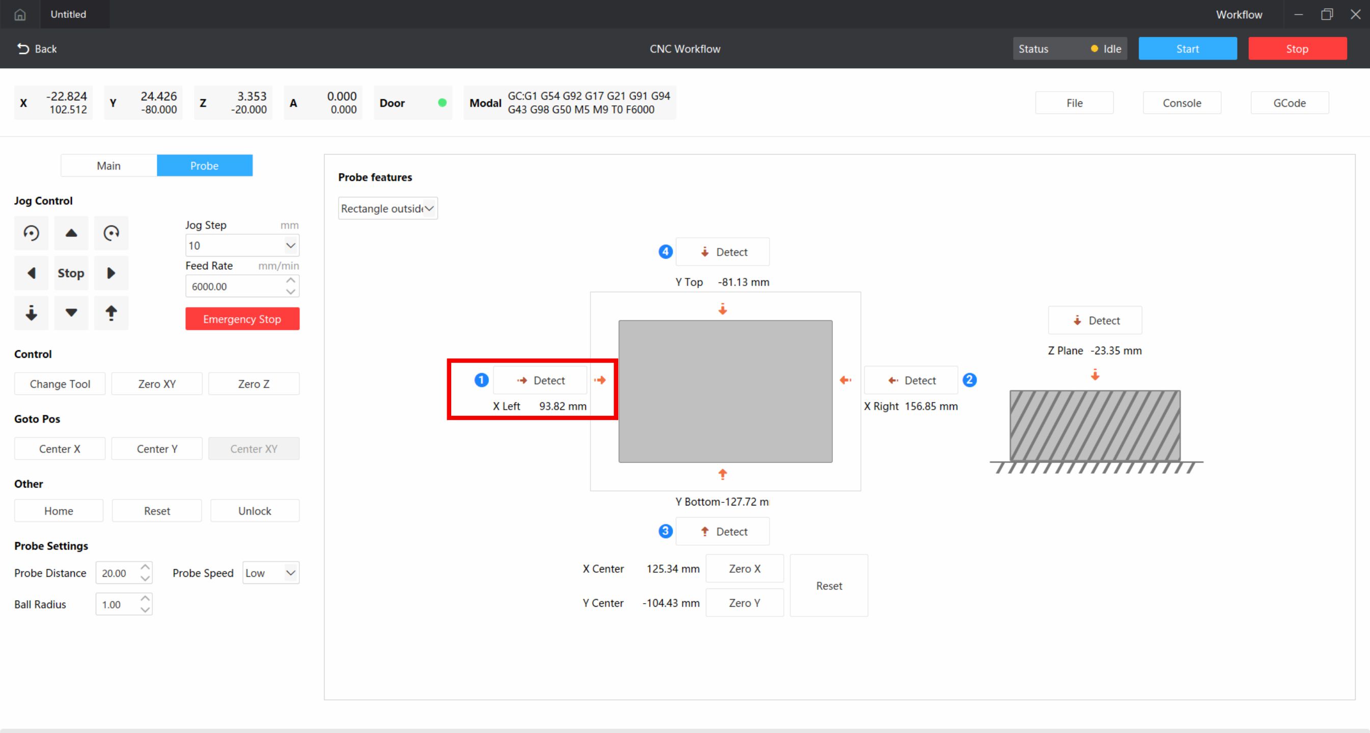
¶ X-axis Left Side Detection
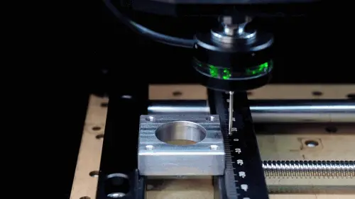
Use the movement function to move the 3D probe to the left side of the workpiece.
And click detect, wait for detection to complete.
¶ X-axis Right Side Detection
After detecting the workpiece, manually raise the Z-axis to a safe height, then move to the right side of the workpiece.

Click detect, wait for detection to complete.
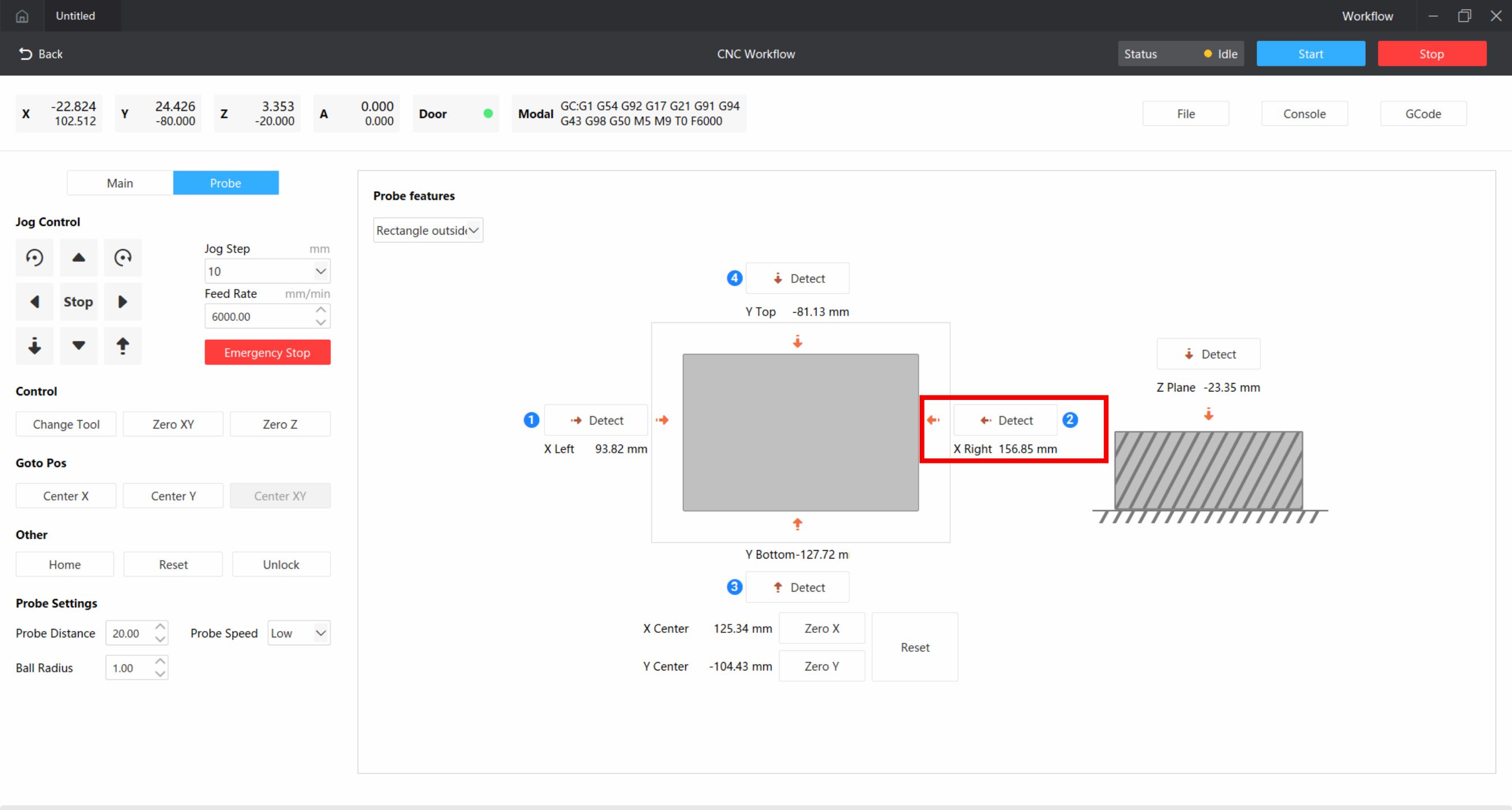
After detecting the workpiece, you will get the X coordinates of both sides of the workpiece, click Zero X below, automatically calculate the center, and set the center as X0.
¶ Y-axis Detection
Detect the front and back sides of the workpiece using the same method, click Zero Y, automatically calculate the center, and set the center as Y0.
¶ Z-axis Detection
Use the movement function to move the 3D probe above the workpiece.

Click Z-plane detection, wait for detection to complete.

After detecting the workpiece, it will automatically set the detected position as Z0.

¶ Tool Change
After all settings are complete, click tool change to replace the first tool to be used and complete automatic height measurement.
⚠️ Rectangular External Centering Precautions:
Circular external centering and rectangular external centering operations are similar. However, note that when detecting the X center point, the Y-axis coordinate cannot be changed. When detecting the Y center point, the X-axis coordinate cannot be changed. For example: after detecting the X left side, raise the Z-axis, then move to the X right side, during which the Y-axis cannot move.
¶ 5. Circular Internal Centering
Select circular internal centering in the software to detect and automatically calculate the center position, manually set the detected center as XY0 point.
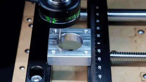
¶ X-axis Left Side Detection
Use the movement function to move the probe inside the workpiece, close to the left side inside the workpiece.
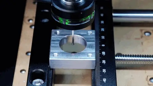
Click left detection, wait for detection to complete.
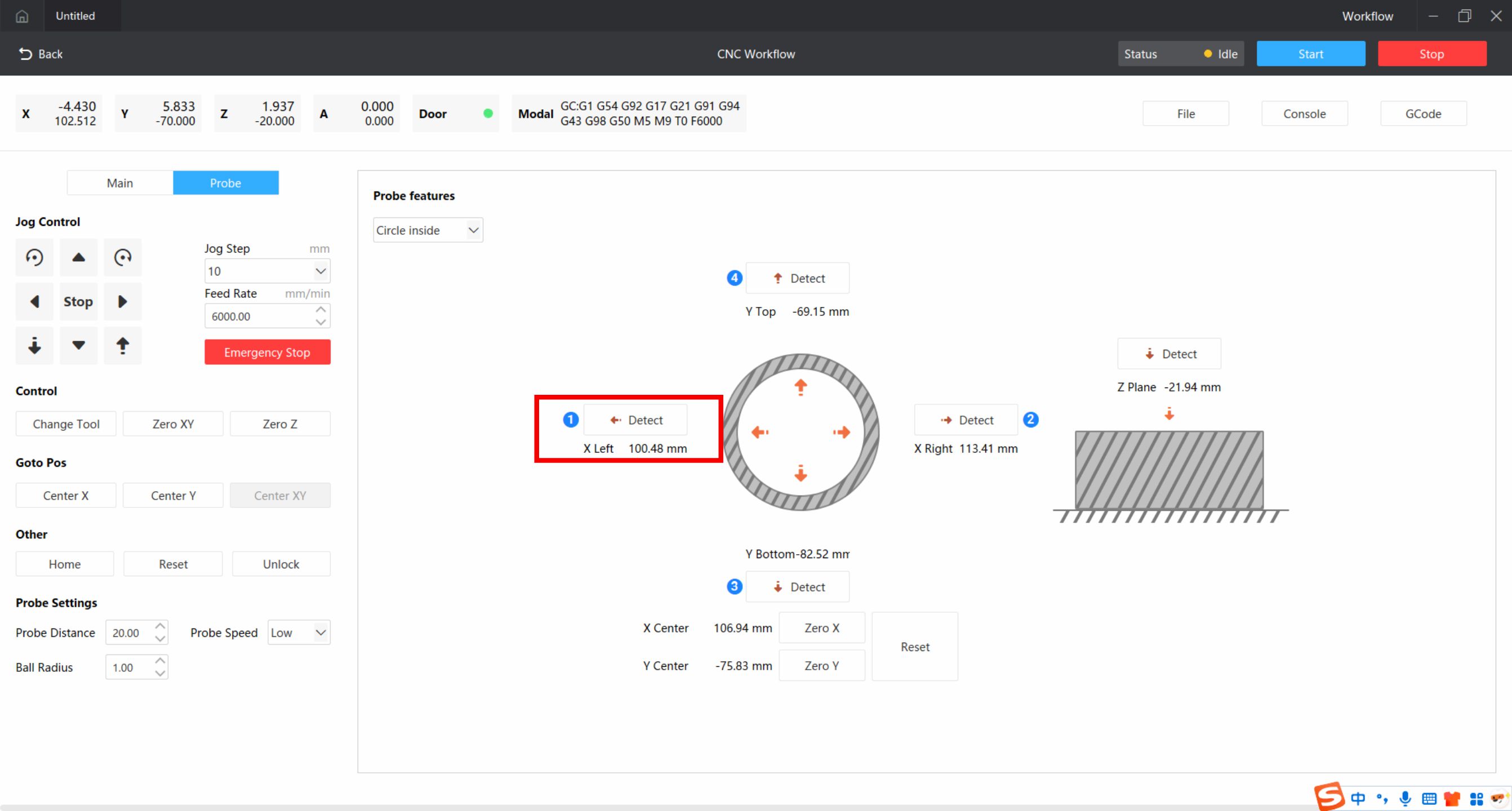
¶ X-axis Right Side Detection
After detecting the workpiece, move close to the right side of the workpiece (do not move the Y-axis during this time).
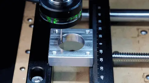
Click right detection, wait for detection to complete.
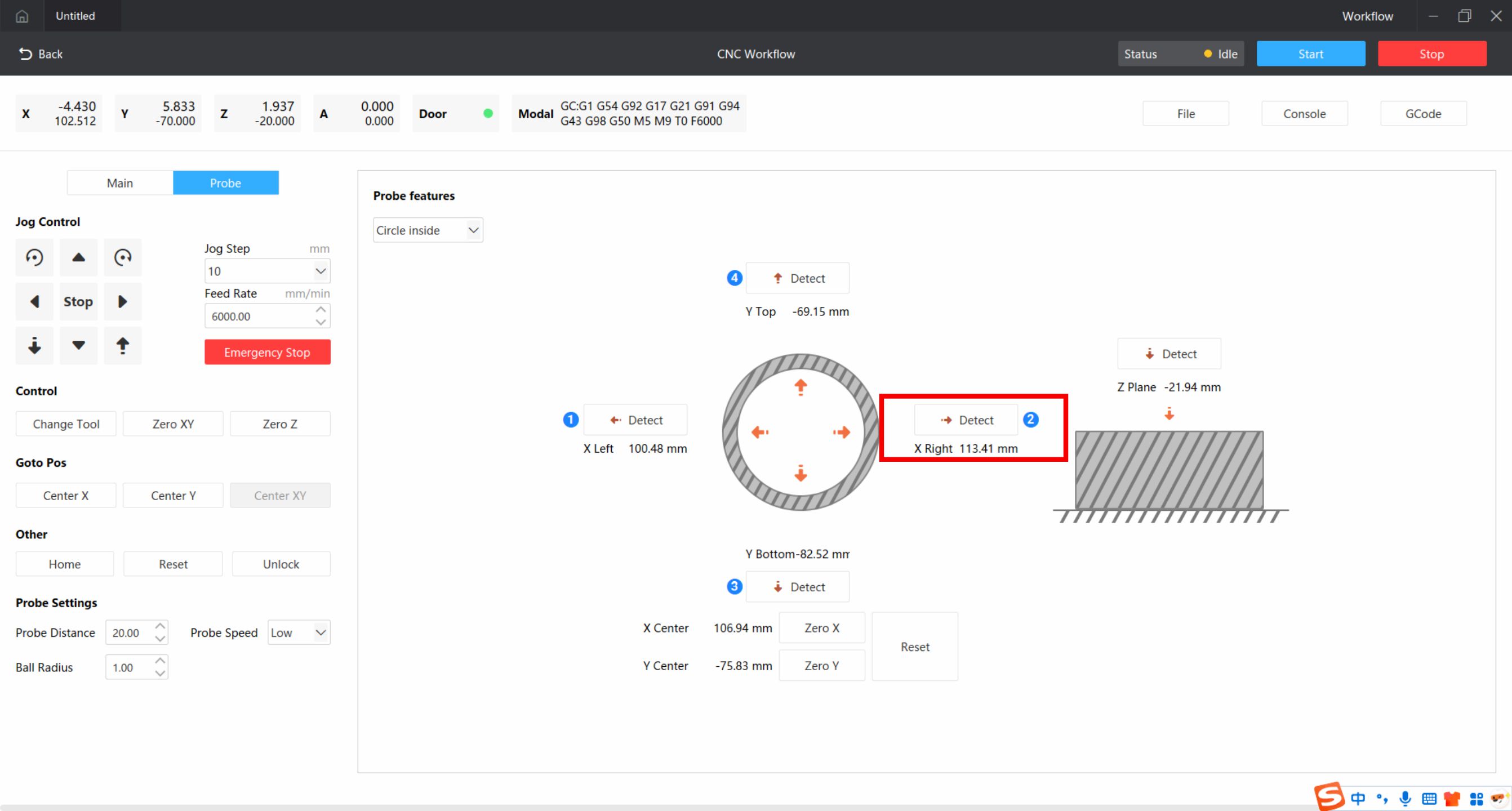
After detecting the workpiece, you will get the X coordinates of both internal sides of the workpiece, click Zero X below, automatically calculate the center, and set the center as X0.
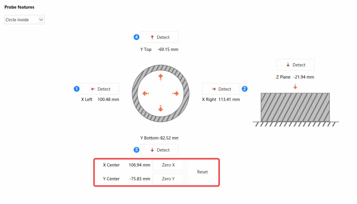
¶ Y-axis Detection
Detect the front and back sides inside the workpiece using the same method, click Zero Y, automatically calculate the center, and set the center as Y0.
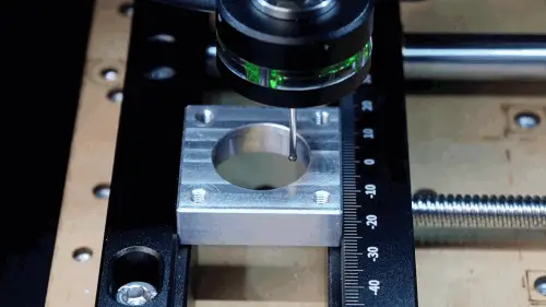
¶ Z-axis Detection
Use the movement function to move the 3D probe above the workpiece.

And click Z-plane detection, wait for detection to complete.
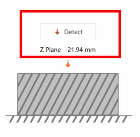
After detecting the workpiece, it will automatically set the detected position as Z0.

¶ Tool Change
After all settings are complete, click tool change to replace the first tool to be used and complete automatic height measurement.
📋 Centering Operation Tips:
Rectangular internal centering and circular internal centering operations are similar.
¶ Precautions
⚠️ 3D Probe Usage Safety Precautions:
- Centering is suitable for workpieces with regular shapes, such as circles or rectangles. Not recommended for irregular workpieces
- During Z-axis surface detection, select the highest surface of the workpiece
- When moving the 3D probe, keep the ball tip slightly below the workpiece, not too low
- Observe in advance if there are objects that may obstruct the 3D probe movement, avoid the 3D probe being hit and damaged before the probe contacts
- The 3D probe is a precision and easily damaged accessory, please move the 3D probe slowly
- If the alarm is triggered by accidental contact during movement, please remove the obstacle in time, return to zero and retry